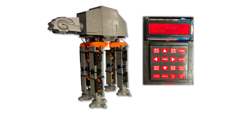
AT-AT BLE Robot
12-DOF robot, PCB Design for 4-device BLE-network, ARM Assembly, TI RTOS in C
Hardware Overview
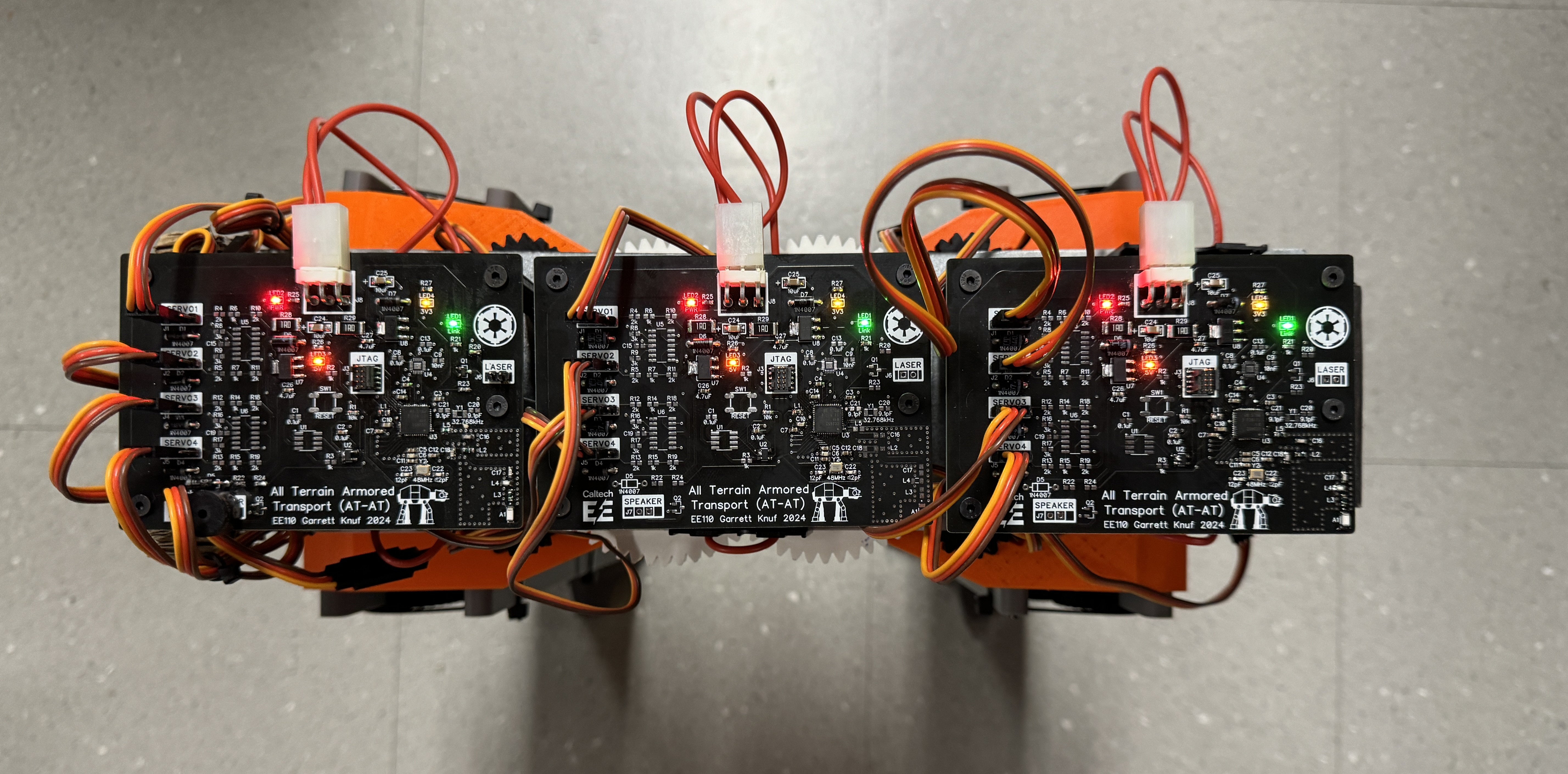
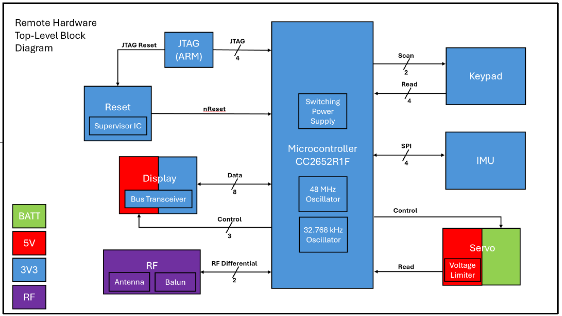
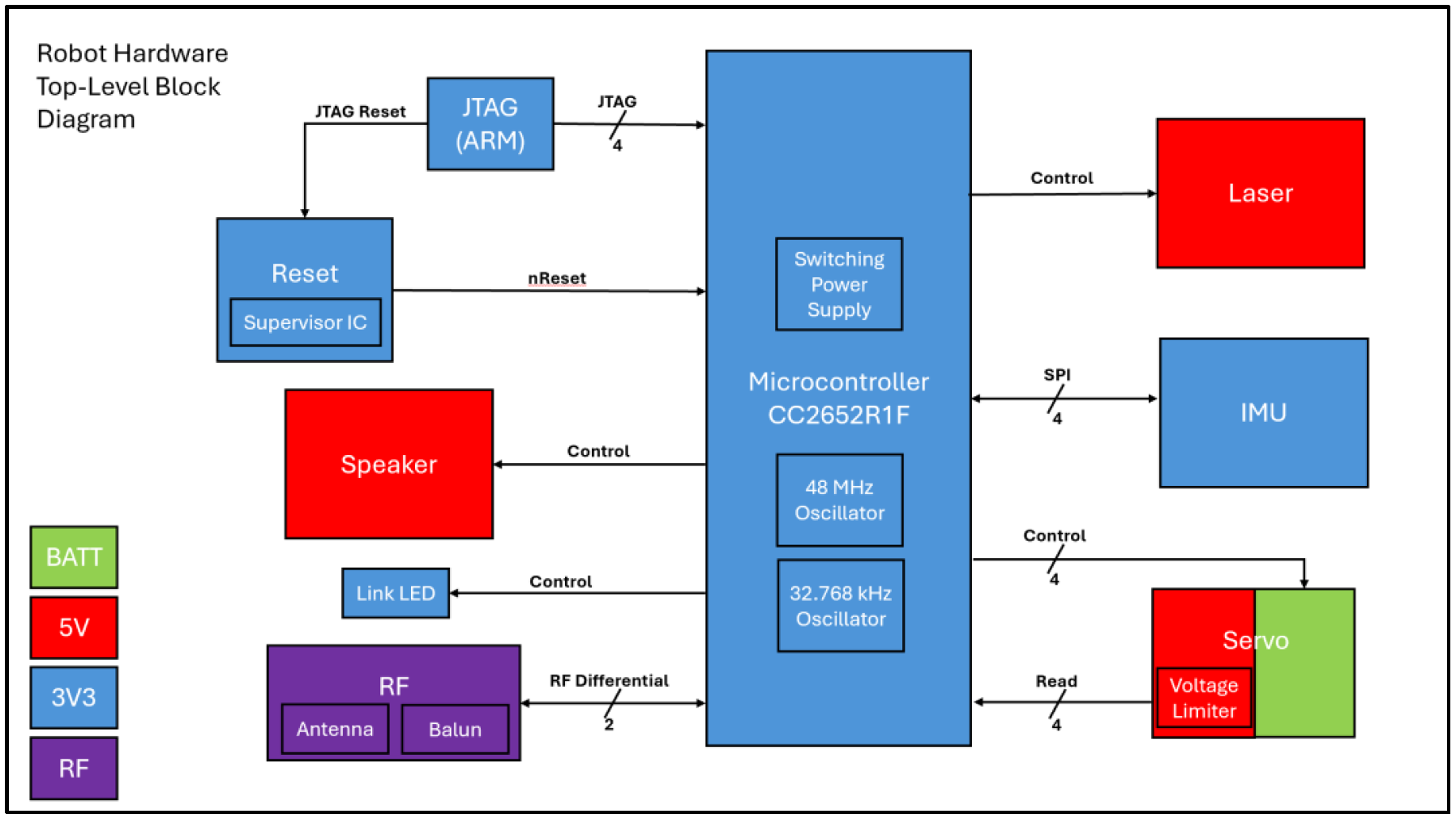
There are two different board designs for the AT-AT system, a remote and a robot controller, which communicate over Bluetooth Low Energy. Each board runs off the CC2652R1F microcontroller by TI capable of 2.4 GHz wireless communication. It runs off a 48 MHz high frequency oscillator and a 32.768 kHz low frequency oscillator. It also has an on-chip buck DC/DC converter. It is programmed by a JTAG ARM connector, and the chip can be reset over JTAG or by the supervisory IC in the reset circuity. The RF design is identical for both boards, though each have different PCB RF layouts. Each board needs to be supplied power in a range of 6.4V - 8.2V. The remote hardware needs to be able to draw 1.5A of current while the robot hardware needs to be able to draw 10.5A per board. The external power supply is regulated down to 5 V and 3.3 V used by various other blocks as shown in the color coding of the diagrams below. Both designs contain a 9-axis inertial measurement unit (IMU) that contains an accelerometer, gyroscope, and magnetometer and communicates with the MCU via SPI. They also contain a block to control a MG996R servo motor and get position feedback from a potentiometer internal to the motor. The remote hardware contains circuitry to control one servo motor while the robot hardware can support the control of up to four servo motors. A 4x4 keypad can be connected to the remote hardware where the MCU can scan the rows to read the columns. The remote also has a standard 16x2 LCD display that can be controlled via the MCU. The robot hardware can drive a speaker or buzzer via PWM signal from the MCU. It also has an additional LED to indicate when a Bluetooth link has been established. Additionally, it can drive a 5mW laser diode controlled by the MCU.
System Block Diagrams
Remote Controller Schematic
Robot Controller Schematic
Software Overview
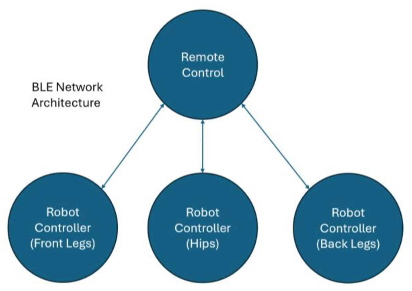
The software for the AT-AT system consists of two repositories: one to control the remote hardware and one to control the robot hardware. The devices communicate with each other via a BLE connection run from the TI RTOS on the TI CC2652R1F microcontroller. The remote board is configured as a BLE peripheral device and the three robot boards are configured as central devices (i.e., the remote advertises and the robot devices can initiate establishing a connection between the boards).
The remote processes keypresses on the keypad, and when a key is pressed, it updates the message on the display and sends a BLE notification to be received by the robot boards. All robot boards receive the same notification data and can choose which data to respond to and which data to ignore. The motion controller of the remote also periodically sends robot position updates based on robot position changes from time-dependent state machines.